
flexible PCB boards be used in flexible batteries
As electronics products continue to get smaller and smarter, the demand for flex PCB has increased significantly. Flexible printed circuit boards can reduce manufacturing costs and allow designers to create complex layouts in limited space. However, the complexities involved in creating these boards require careful attention to the materials used and their properties. Having an understanding of the different materials that make up a flexible board can help you select the right one for your application.
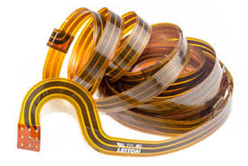
In general, a flexible pcb board consists of multiple layers of conductive copper foil sandwiched between insulating substrates. The substrates can be a PI or PET film, thin flexible epoxy, or glass fiber. In addition to the conductive layers, a flex circuit requires a protective layer called coverlay that insulates the outer surfaces and protects them from corrosion and damage. The thickness of the coverlay varies according to the board’s requirements.
Flex circuits are often used in mobile phones and other portable devices where space is at a premium. They can reduce the number of components and connectors in the device by providing a more compact layout. Additionally, they can improve signal timing and reduce noise due to the flexible nature of the boards. This means that you can design more sophisticated and robust devices without sacrificing battery life or connectivity.
Can flexible PCB boards be used in flexible batteries
Another important use of flex circuits is in medical wearables. They collect all sorts of physiological data to provide valuable insight into your health. These devices need to be small, comfortable and unobtrusive. Additionally, they need to be able to collect the data in a variety of conditions. Flex PCBs are able to meet these requirements, allowing you to develop smaller and more advanced medical devices.
In automotive applications, flex circuits are also being used more and more. They can replace wire harnesses, which are heavy and limit the number of connections in a vehicle. They also provide more reliability and are more resistant to vibration than traditional wiring harnesses.
While a flexible PCB has many advantages, it is important to keep in mind that there are specific rules and guidelines for using them. For example, it is important to avoid 90-degree bends as they increase the likelihood of damage. In addition, it is important to maintain a distance of at least 10mils between conductors and the bend area to prevent stress points. Finally, you should not add plated through holes in the bend area as these can lead to breaks and cracks.
Fortunately, you can easily model and prepare your flex PCB for production using the Altium Designer + Draftsman software suite. This software package includes everything you need to create a complete schematic, an accurate drawing and a fabrication data sheet. It also features a full set of CAD tools, automated drawing functions, and an extensive library of symbols and parts for the most advanced flexible and rigid-flex circuits. Start a free trial today to experience all that this software has to offer for yourself.